Tag Archives: Thingiverse

Extract STL from Preform project files

NOTE: this post was based on one of the first preform software release that did not have encrypted STL content. Current SW version have been ‘upgraded’ to include an encryption that present the extraction of the STL… So this information is only there for historical purpose. If you want to have access to the final STL with the support structures you should ask Formlabs marketing department directly unfortunately.

The Form1 printer is supposed to be a click and print easy consumer solution. You get a sleek hardware (that still needs some tuning) and a polished software (Preform) that does not let you tweak a lot’s of options. So if for some reason the auto-generated supports are not working or you want to use a non-official polymer, then you are locked by the closed nature of the product.

When I’ve discussed with Formlabs during the SF Maker Fair, they confirmed they had no intention to release the USB protocol and the .FORM file format specification. The result is that if you want to use a Linux OS or another slicer, you are restricted (ex: generate internal supports function does not exist in Preform yet). These limitations do not exist with the B9 printer, as they decided to release everything as open source.

So what can be done? Well we are limited to reverse-engineer the FORM file or the USB protocol. It’s tedious and random: the end result is not guarantied but by doing so You can learn things about the Form1 and maybe fix some short-coming. A few stuff that open protocol/file could do:

  • enable other OS (no need to use visualization in Linux for ex)
  • custom slicer to fine control the supports, generated path, calibratio
  • Compatibility with different resin/polymer by adjusting the curing parameters
  • new cool features like the vat-fogging map

Anyway, with this post let’s start simple by extracting the STL meshes embedded in the .FORM files.

Extracting STL Mesh data from the .FORM

Using  something like Frhed free HEX editor let you peak at the file content, and a little bit a search gives this 80 characters string with “stl” inside… Yes this is, if you remember the STL file format the first field of a binary format file.

formSTLHeader

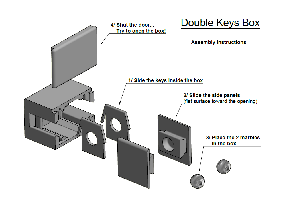
And when you duplicate the same object, or add another STL, you can see that each STL instance is stored in the .FORM file. More interesting is the fact that preform keeps the STL in its original dimension and orientation. So you can see that even if I scaled and rotated one of the pieces (from here), the extracted STL shows the supports scaled and with an angle.

multiSTLinMesh_rotateNScale

This is telling us, that somewhere in the meta data of the .FORM file you have the position, rotation and scale information. This is stored in binary (not text) format and thus is more complex to extract. I might try to find where it is stored in a later version of my STL extraction program.

The Utility to extract STL mesh data from .FORM files is coded in plain C, so you should be able to recompile it on anything without much issues. The current EXE was compiled using Visual Studio Express 2010 x86, so you might need to install the VS 2010 redistribuable package before using it.

Utility usage is: extractSTL xxx.form
This will extract the STL meshes and save them in “xxx.form_meshN.stl”

The EXE, source code and VS project files are available here.

Happy forming!

[<<Prev. – Form1 might need calibration]    [3D Printer articles]   [Form1 Calibration Procedure – Next>>]

Evaluation of Preform 0.8.1

As I was explaining in my previous post, the form1 printer software is still a work in progress. Some bugs have been squashed with the 0.8.1, but some remains and I’d like to go though the some of the current challenges that a fellow formers might encounter. The first ones are the most critical in my opinions…

Object skin is not always sticking to the filling

[I’ve submitted this bug #1123 to the community board]

I’ve chosen the impossible heart brain teaser available in Thingiverse to see how very simple and smooth pieces would print… First it was not a brilliant idea to print it without supports. I had to use a clamp to pry apart the pieces from the platform and in the process damaged a bit the puzzle surface.

impossibleHeart_plateAndAssembly

But the real issue was, as some of the Reuleaux spheres in my previous post, the perimeters on some of the pieces didn’t stuck and I ended-up with a ugly result. What you see behind are the back and forth inside filling profiles. My hunch is, depending on the pealing direction, the perimeters might not be completely merged with the filling leaving a weak spot in the structure…

impossibleHeart_peallingPerimeters

If I was Formlabs, I would try to extend the filling paths so that it overlap at least the last perimeter to make sure everything is correctly glued together.

impossibleHeart_extendedFilling

[.form file]

25 microns prints non sticking to the platform…

This point a a bit a hit or miss. I’ve followed the advice in the community forum that using the “grey 25 microns” material profile was increasing the chance of sticking and so far I had 2 out of 3 prints working. The sticking might be affected by the location of the print on the plate and the orientation of the base platform. If you have a long platform, turn it so that the peeling starts on a small side.

To solve this it would be great to have more control on the laser, like being able to set the speed of the scan, the number of repetitions, the number of perimeters. That would open quite a few possibilities and for the most advanced users it could be a great way to experiment.

Overlapping supports are creating pockets of uncured resin

[I’ve submitted this bug #448 to the community board, and it’s marked as closed]

That one is strange but apparently it’s already fixed for the next revision. The problem arise when the software decides to place 2 supports so close that they are overlapping. In this case the internal filling back and forth of the laser is missing at the intersection. That will create a hole of uncured resin and I it’s safe to assume the support strength is gone…
[.form file to test]

supportsHoles

Peripheral loops are overlapping on very thin walls

[I’ve submitted this bug #1124 to the community board]

Preform is drawing 3 loops around perimeters. These loops are continuous and when the geometry has a very thin wall, these perimeters will get inverted and even create filling outside of the geometry… (Yes I know it’s not clear, just look a the picture to understand the issue…)
[.form file to test]

outsideFilling

That’s all for today 🙂 If you have any comment or extra bug to report on this release please comment I’ll investigate them!

[<<Prev. – First steps with Form1]    [3D Printer articles]   [Form1 Needs Calibration – Next>>]

First steps with the Form 1 Printer

So here it is after many months of waiting the Form1 Stereo printer is sent to backers! and I received a few days ago my puppy, and now the 3D touch has some serious competition.

More on that later, but I’m thinking on selling my 3D touch printer with ~15 filament spools of various colors/materials. So If you are interested mail me, free training included if you are in the bay area 🙂

I will not do a full tear down of the printer, but if you are interested to see the guts of the form1 Bunnie’s blog has an interesting post.

cartboardWith3dTouch

The cardboard boxes are massive and Formlabs decided to avoid foam or bubble wrap to lock the printer in place. The printer was held by 2 plastic films, but you can see in the picture under that during transport it shifted out of the slot. Nothing serious in my case but I have already read some reports of people complaining they received their printer damaged. I’m not exactly sure if this packing method is completely fool proof, especially if the box are rotated during transport/handling.

InsideCartboardBox

The unpacking was really easy, just a few tape pieces to remove… But dang, that’s a sharp looking printer! I’m especially impressed by the build quality. As you can see in the following pictures, they didn’t try to cut on the details. The only small remark I’ve is that the printer detect when the orange hood is closed using a hall sensor and from time to time the magnet is not completely aligned so you need to fiddle/move a bit the hood to get it detected.

Form1ReadyToOperate form1BuildQuality

Now let’s move onto the printing. The samples I’ve seen during the Maker Fair were great but I have to say I feel the Preform software (V0.8.1 at the moment of writing) is still somehow limited and you need to practice a bit to understand how to get the best out of your printer.

My first test was a 25 microns print of one of the Cyvasse game piece but for some reason the support (surface of ~ 2 * 1cm) was not sticking to the platform and the cured resin ended up floating in the tank… So after 2 tries and a fishing party to retrieve the layers, I decided to start with something easier and stick with the default 50 microns layers for the moment.

My first success was with a pocket monster figurine by Andreas. I’ve scaled it down to 50% (.form file) and the result is quite stunning when you are used to the FDM quality. Once cleaned from the resin with alcohol and dry the pieces are a bit cloudy and not very shinny (left picture). I used a Varathane Gloss polyurethane water based spray (interior / Heavy Use Formula) to get a great shine (right picture). With one layer, the details are not lost and you really have the impression that it’s made of crystal.PocketMonster

After that, I was ready to test the limits of the printer. So I tried the simplest structure I could find on George Hart math page. When processed by Preform, the Goldberg polyhedron (.form file) had a large red/unsupported ring area but I decided to print it anyway…goldbergSphereError

It didn’t worked out and I could just  clean up the mess after. golbergFailOnTheTray

As you can see the resin is rather flexible and not fully cured after print. I couldn’t remove the remaining of the sphere from the support without tearing the sphere in half. So lesson 1 is: don’t pull 1mm thick walls… Maybe I should have tried to wash the result and wait until dry?golbergFailFlexibleResin

I was surprised to see how flexible the resin is after print, so I’ve put some of my failed pieces outside in the sun to see how the resin age. As you can see under, after the prints, the parts are white, but just 2 days outside (gyroid – top right) and the resin is much harder/cured but with a yellowish tint. After 4 days (sphere – top left) the tint is even stronger and  all the flex is gone, the cured resin is actually very stiff.form1_aging_resin

Now let’s have a look at print defects that you can get with the form1…

I’d like like to stress that Formlabs team is making progress and the new Preform software revision (0.8.1) is actually solving one of the issues, each layers had a visible seam but the new cleared that point.

seam_form1_defects

Visible seams in Preform 0.8 (Releaux spheres print in 50 microns)

These seams were visible but you couldn’t feel them on the surface so it was more a cosmetic defects. The real issue comes when some parts of the print are not cured properly. In this case the end result is rather ugly on some sides…

reuleaux_form1_defects_0-8-1

Reuleaux Spheres printed with 0-8-1 (50 microns, default generated supports)

To conclude this post, I have to say the form1 is an impressive printer, the details of the parts are great and the build quality is stellar. That said, I know being an early adopters has its disadvantage and even if the printing process is not yet “plug-and-print”, I have high hopes for the future!

[<<Prev. – NA]    [3D Printer articles]   [Preform 0.8.1 – Next>>]

3D Printing ecosystem

Today let’s have a look at the 3D printing ecosystem. In previous posts, I’ve covered specific points like online communities, 3D scanners and the evolution of manufacturing that led to 3D printing. This will be a global overview of all important actors that have stakes in additive manufacturing.

An Ecosystem, Really?

An interesting aspect of 3D printing is that it’s spreading everywhere. Individuals and businesses are exploring and using it alike. Individuals population is restricted right now to makers/hackers/doers but it will hopefully change overtime.

Speaking of makers, we went to the Maker fair this weekend in the bay area. And this year Formlabs was participating, and I have to say the quality of the prints was stunning! And this morning I just received the confirmation that my printer is being shipped so I’ll post update as soon as I get it.

Now let’s start with this ecosystem! I’ve split it in 4 areas with:

  1. The needs : why would you even consider it?
  2. The software : How to do generate the input data file?
  3. The hardware : Nature of the beast!
  4. The users : with a distinction between Individuals and the business side.

3dPrinting_ecosystem

1/ The Needs

For professionals rapid prototyping is a great way to visualize early in the development process any design. But in some case it ca also be used to manufacture one of a kind mechanical piece that would be impossible or too expensive to mold or machine from a piece of metal.

Because 3D printer are not yet main stream, right now only technical inclined individuals (doers/makers) will have the patience to tweak a printer. They will use it to create things like games, repair household, learning tools, arts or even print any crazy projects! Note that manufacturers are really trying hard to make these printer easy to use, so the population capable of using one will increase.

needs_pictures
Sources [1], [2], [3], [4], [5], [6]

2/ Software

Without models, a 3d printer is not really useful. Professionals have access to complete CAD software or modelers that costs thousands and need an extensive training. They can also acquire a scene/object using 3D scanners.

Individuals have simpler and mostly free tools available, some of then browser base to create new shapes. Some services like 123D let them rebuild a geometry from a series of picture. Note that most of the pro software are available for free or cheap provided you are or know a student willing to lend his name 🙂

software_pictures

3/ Hardware

Now the range of printer available is only limited by your budget. Each printer can go from $100ks to a few hundreds for the cheap FDM kits.

Professional have access to cindering machine that can print metal/ceramic on very large volumes. The cheap printers are today limited to filament extrusion but there is a intermediate class of device (for prosumer) few $k offers very nice accuracy like the Form 1 stereolithography printer.

printer_pictures
Sources [1], [2], [3], [4]

4/ Users

As for the 3D printing world actors, there is a consolidation going on to group the resources.  Some R&D centers that have a printer for themselves but, like machine shops, it does not make sense (yet) for every business to have a printer in house. So website are proposing a printing service on a large selection of material. These website are even trying to attract casual/pro designers that can expose their creation and let people order them with a markup. Printer manufacturers are also creating online communities to let user upload design. Thingiverse is one of the biggest community and very useful to find preexisting models.

users_pictures

Here is my view of the 3D printing ecosystem, if you have any comments please comment!

[<<Prev. – Mass customization Age]    [3D Printer articles]   [Giant Dice! – Next>>]

Mass Customization and Fast Prototyping Age?

This article is less about technique and more about thoughts that I had while designing my last project. It was based on an idea I had a few days ago: a reminder that you place in top of a medicine tube to remember the last time you took your medicine. This design was published on Thingiverse.

pillReminder_assembled pillReminder_dissasembly

To get a practical design I had to go through multiples iterations and the 3D printer was a great way to directly have a confirmation that my changes were going in the right direction. In this case I just had to wait 50 minutes to see the alterations results…

PillReminderEvolution

So what are the consequences of these short prototype cycles? Can these 3D printer be used by the end customer to get exactly the right custom product?

When we think about the “2D” version of printing we can see and evolution with:

  1. Scribes and monks reproducing parchment by hand
  2. Gutenberg and the print press with mass production of books
  3. To reach mass customization with modern printer technologies like inkjet or laser

2D_evolution
Images sources: [1] [2] [3]

Now if we look at the 3D object reproduction, we can see that the first step was sculpting to get a custom object. Then injection molding and casting helped to mass produce the same shape and now the 3D printers are opening the realm of mass customization…

3D_evolutionImage Sources: [1] [2] [3]

Note that I’m not trying the start a flame war when I make a parallel between hand-writing and CNC. Modern machining is in a sense the final step of evolution of sculpting. The helmet picture is one of the most impressive demonstration of 5 axis machining that I’ve seen so far. Built by Daishin, the speed and the details that this machine is capable of carving are absolutely stunning.

Now 3D printing is currently at his infancy slow and some time limited. But it as already access to many materials from plastics to metal and ceramic. New fields are opening with organ and organic tissues printing. So who can really know where it will stop?

[<<Prev. – First Prints]    [3D Printer articles]   [3D printing Ecosystem – Next>>]

Impossible Dovetail Joint

For this week Impossible object, we will revisit the dovetail joints and have a look at some interesting variation on the theme. This time we will use the “master sketch” technique in Inventor to build our different pieces.


This technique is using a single part with all the sketches required to model the whole assembly. Each piece is then derived from the master. To update the model, you just have to update the master sketch, and if everything is properly built, your whole assembly should follow.

Result_picture1

The inventor result files links are at the end, with the STL and the thingiverse link.

  • To start, create a part with a bunch of user parameters to control the design. Then on the horizontal plan XY create a sketch with the outline of the 2 main blocks (length*width).
    impossibleDovetail_01_userParam
  • The dovetails are extruded on a non-vertical plan, so the easiest way to control the result is to create a sketch in XZ plan and draw a segment with ‘Tilt’ angle from the horizontal. Then use this segment and the origin point to create the work plane using “Normal to axis through Point” tool.
    impossibleDovetail_02_TiltPlan
  • The next sketch will be on this newly created plan. The left triangle and the left side of the center one are drawn and the rest is a mirror copy. The base of the left triangle is at length/5=10mm. To allow some clearance in the pieces, all triangle have been “offset” inside by “clearance” parameter (0.25mm here).
    impossibleDovetail_03_DovetailSketch
  • The final master sketch part should now look like the view under.
    impossibleDovetail_04_Mastersketch
  • Now we create a new part to model the first piece. From the manage tab, select the “Derive” tool and choose the master sketch part. Then make sure that the User parameters and the Sketches are shared (yellow plus) and validate. The master sketches will appear in you new part. Now any change in the master sketch will update the part (you will have to press the update button / thunder bolt)
    impossibleDovetail_05_Derive
  • Each sketch will be used multiple time to build the piece, so don;t forget to make them “visible” again once they have been used by an operation. The first thing will be to create the “male” dovetail in the center, so the first step is to extrude the small version of the center triangle by a very large amount on both side.
    impossibleDovetail_06_Centerdovetail
    Then extrude the left rectangle by height and keep only the intersection. to create the dove tail.
    impossibleDovetail_07_CenterdovetailFinished
    impossibleDovetail_08_CenterdovetailFinished2
  • Now the main body can be created by Extruding the right rectangle by “height”.
    impossibleDovetail_09_body
    To create the 2 side female dovetails, just select both the external rim and the internal triangle on both side and cut into the main piece.
    impossibleDovetail_10_body
  • To finish the piece you can add a fillet on the internal side of the dovetail.
    impossibleDovetail_11_finish
  • The second piece is created the same way, from a derived part except you have to do the “negative” geometry.
    impossibleDovetail_12_PieceB

And here is the result assembled with a “wood” finish 🙂

impossibleDovetail_Result01

impossibleDovetail_Result02

I’ve printed the result to check that the piece would indeed fit and yes it works!

The STL files are available in Thingiverse here and the Inventor files are here.

[<<Prev. – Symmetric Penrose Triangle]    [3D Printer articles]   [TBD – Next>>]

First prints & lessons learned

After many tests print I finally got to print some real stuff these last day. The first object was something completely useless but full of gears and very cool (so by my standard indispensable).

One of the mistake I made, was to print the raft and the pin out of PLA. I could not get them to stick to the bed without but couldn’t separate the result so my yellow internal pieces have a black layer 🙂 GearCube_Assembly

The end result is a nice transformer like cube…GearCube_EndResult

My second print was one of my puzzle: double dovetail with a twist.

The pieces are large and I got warping as my bed is not heated… Nevertheless, the comb infill is nice to see…DoveTail_warping

The dovetails ended pretty flat, and just a little bit of sanding was necessary to allow a nice sliding between the parts. DoveTail_separated

And here is the final assembly 🙂 I need to design more puzzle!DoveTail_assembled

And here is the puzzle in action!

[<<Prev. – A New comer]    [3D Printer articles]   [Mass Customization – Next>>]

A new comer !

I’ve not posted for a few days now, because I was experimenting with my new printer. I came across this 3D touch printer from Bits from Bytes and it was the perfect tool to start experimenting on 3D printer while waiting for the Form1.

3dtouch_printer

It’s a Fused deposition modeling type that can print ABS and PLA plastics. Like any technology there is usually no silver bullet and these printer are quite complementary to stereolithographic ones:

FDM pros:

  • Wild variety of printable materials, with different colors and mechanical properties. The main ones are PLA and ABS. PLA is a recyclable plastic made  from corn than can be dissolved in hot water over the course of multiple days. ABS is stiffer and better for mechanical pieces but not as ‘green’. But you can find also ‘wood’ filament, nylon or even recently an elastic/flexible filament has been announced. From the way the extruder head works in this printer I don’t think I will be able to print this elastic filament.
  • The printing materials are “cheap”, the starting price is around ~$30 for a spool of 1kg of PLA. Specialized materials/colors are of course more expensive but at least the basic material is affordable. There are also initiative to build/sell filament extuders so you can even recycle your own trash plastic. I would be worried about the fumes that some plastics are releasing while melting and wouldn’t try these apparatus with PVC for example (but maybe HCl is only created when the plastic is burned?)…
  • With FDM you can print hollow or partially filled objects. The internal structure will add structural strength while keeping the weight down. It’s also a great way to save maters and produce cheaper parts.
  • The printer can have multiple extruder heads, so an object can be made out of different colors/materials. It’s also possible to print supports in PLA and the main object in ABS, so once the print is finished, the support can be dissolved without affecting the object.

FDM cons:

  • The print accuracy & reliability can be difficult to reach. These printer are still not main stream and requires a lot of fiddling and tuning to get the best result. One of the main challenge is to have the first layers adhere to the print bed. If the temperature, calibration, surface state is not perfect the print will not work. Once the adhesion is working, the surface quality, over-hang and seams marks are some of the few challenges that needs to be cleared…

Stereolithography pro:

  • The laser curing enable high accuracy and reliability
  • The printer can have fewer moving parts, so it’s easier to calibrate/operate

Stereolithography cons:

  • Cost of the resins, even with the Kickstarter preferential cost, the liter of resin has been announced at ~$120. The materials are also usually not really nice and a bit toxic when uncured. The choice of resins are also more limited in color and mechanical properties.
  • With the ‘vat of resin’ design, it’s difficult to build an hollow object, unless there is an escape hole to flush the resin at the end. This will translate in higher cost of the final parts.

But enough talk, let’s have a look to my first prints 🙂 I’ve spend quite some time calibrating the bed to make sure it was horizontal to the head axis. The first print was one of the example given by BFB in ABS. While the layers were quite coarse, the end result is quite impressive, very sturdy and light.duckyPrint

For the second try I’ve selected the one piece Penrose triangle that I’ve put on Thingiverse.

onePiecePenroseTriangle_withSupportThe support was a bit difficult to remove (I might try to get it less dense next time), the final shape is a bit too curvy, but with the right angle the illusion is nearly working.

penrose_final

penrose_final_side

[<<Prev. – NA]    [3D Printer articles]   [First prints – Next>>]

Brain Teaser: Double Keys Box

Today’s puzzle is an other trick opening box. From the puzzle classification list by Slocum this is the family where the goal is to take apart the assembly. In this box you have a hidden mechanism that let you open it if certain steps are followed.

The box is rather plain for outside, but the interesting part is the internals. With 6 sliding pieces this is by far the most complex assembly I’ve built to date. As you can see, the master sketch part starts to be a bit crowded! In on of my next post I will probably describe the process of creating complex assembly and shapes with Inventor.master_doublekey

The assembly instruction gives a better overview of the different pieces.Instructions

The Main body (box) is were all the other pieces are sliding into. On both side a panel and a key have a round slot to catch one of the 1/2″ marbles. The pieces are symmetric so that the same geometry can be reused. Once everything is pushed inside, the door slide from the top.

To keep the door shut the pins have a spring bar that I saw in another Thingiverse object by Ttsalo.

As I do not have a printer yet, I use the schematics and cut views to make sure everything will work.

Assembly

The Interesting part is to have a look at the lock pin cut:

lockpin_doublekey

In this cut one of the ball is placed in the slot. The pin is in locked position (note: the spring is not bent, so it’s going through the back wall). The door cannot slide up, the only way is to pull in the pin using the side panels. But unless both keys are activated at the same time, the door should not move…

As always I’ve uploaded the STL on Thingiverse here.

Happy brain teasing!

[<<Prev. – Padawan box Puzzle]    [3D Printer articles]   [TBD – Next>>]

Impossible objects: The Penrose Triangle

The Penrose triangle is one of these shapes that seems impossible to build but that you can model for fun and then print. Theres are aready a few version on thingiverse but they are with an open loop (here or there). I will here go over a short tutorial with Autodesk Inventor to build one version of the said triangle with a closed loop.

  1. On a new part file we will first draw the “L” outline of the triangle with 2 square on each end with diagonal as construction lines. I try to keep most of the distance parametric so i can update the object faster after (in this case length=40mm, & side=5mm). Then extrude the whole profile by side amount
    penrose_step1
  2. On the bottom side of the L, create a sketch then project one of the center point that will be used for the next construction step and as a profile of the final loft.
    penrose_step2
  3. Create a three points plan using 2 opposite corners of one square of the first sketch and the center point from the sketch under the L shape.
    penrose_step3
  4. To build the sweep of the third side for the Penrose triangle, we need a profile. Add a sketch on the plane we just created. Project the 2 square center points and draw a construction line in between. Then add a three points spline that goes from one center to the middle point to the next center point. Activate the handle of one of the end points and add a vertical constraint on the handle. The spline should make a nice symmetric curve.
    penrose_step4
  5. Exit the sketch, and build a sweep using the top square as the profile and the spline as the path.
    penrose_step5
  6. Enjoy your new Penrose triangle. You may want to experiment with the length and the side to get a good looking result. Try to minimize the curve of the spline without creating a self intersecting profile.
    penrose_final

The STL file is available on Thingiverse here, the Inventor part file is here.

Edit 4/19, I’ve finally printed this object, see here!

penrose_final

penrose_final_side

[<<Prev. – Spheroforms]    [3D Printer articles]   [Symmetric Penrose triangle – Next>>]