Tag Archives: bugs

Precision VS accuracy : why I sold my Form1

Disclaimer: I had one of the first Form1 printer sent to backers so my point of view might be biased and I’m sure Formlabs have perfected their calibration process and maybe even changed some mechanical parts of the printer to answer some of the point raised in this article. Take all of this with a grain of salt, read some of the forum posts and make your own judgment!

It’s been a while since I posted on this blog but wanted to update my (few) readers on my current 3D printing status. I’ve finally sold my 3D touch a few weeks back, I had sold my Form1 previously in October to people that needed one to develop alternative resins. I’m waiting for a Zim dual head printer that should be there is a few month, so I’m not abandonning the 3D printing world. It’s just a pause 🙂

So why posting on an old subject?

After a few months of use, I reached the conclusion that the Form1 with all its promises was not going to work for my needs (more details under). But at the time, the number of printers in the wild was small and I couldn’t say if my experience was a fluke or more an intrinsic issue of the design. Then it happened: more and more posts in the forum talked about bad galvo calibration, or printer that would lose calibration after some time. The final stroke was a post made by Kevin Holmes (PDF) were he had to manually adjust the analog PID controllers of each axis to correct his axis scaling and another one (PDF) where he had to replace a galvo on his printer… There is also a growing concern to know if the printer can be used for engineering purpose.

When I pledged on Kickstarter, my idea was to use the Form1 to design brain teasers. In other words, mechanical assembly where all the pieces have to slide and fit perfectly with reduced tolerances. But what the Form1 brings to the table is slightly different: the galvanometer system is analog and moves continuously drawing very  smooth curves. In other word while the system is precise, it does not mean the result will be accurate.

Precision is not Accuracy

First, the difference might seems like a semantic war (see how the “Does zero padding help in improving frequency resolution?” discussion on the DSP group of Linkedin turned into a flame war). The topic is also relevant to my area of work when it’s important to know the range of possible steps/pixel a cursor of a touch screen can move to (precision or quantization) and what is the maximum deviation from the real position (accuracy). To make it more clear the schematics under should explain what I mean:

Precision VS Accuracy

So Precision is akin to the number of steps the laser point can move, and in a Form1 you could consider it as nearly infinite as the analog PID are effectively smoothing the output and the mirrors have a finite frequency response. Now, even if the laser is moving smoothly from one point to the next, it does not mean the laser is aiming to to right location on the bottom of the tank. These accuracy / linearity errors can have many causes.

Accuracy errors in the Form1 cause and mitigation

The challenge of creating a cheap stereo-lithography printer is the temptation to use cheaper elements. From my point of view, the current design can be improved in these areas:

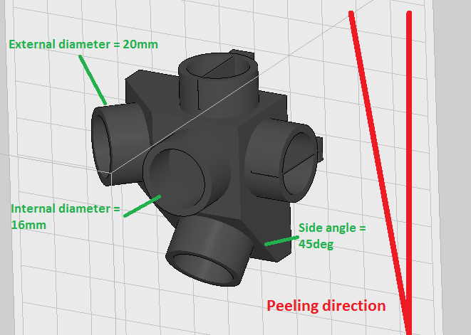
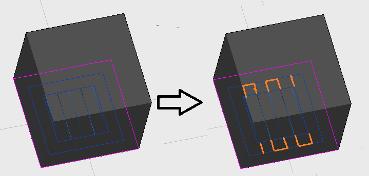
  1. The pealing process is really creating tension force that leads to deformation or requires heavy supports that cannot be cleanly removed from the part. Adhesion to the build platform and damage to the PDMS are also sources of failure. Some of the professional printers are using a dive-in structure were the part is sinking in the resin and the new layer is cured from the top but you need to maintain a large tank of expensive resin.
  2. To make is more compact, the printer is using a mirror to bend the laser path. The beam is now touching the bottom of the tank with a variable angle. As the tank is composed of multiple material, the refractions will deform the laser spot and introduce non-linearity on the border of the print area that could be challenging to correct.
  3. The printer does not include any optics to correct of the barrel effect (F-theta lens), as the laser paths will be varying in length, the focus spot size might change depending on the location.
  4. Last but probably the most important element are the galvanometer amplifiers. Choosing a analog PID controller was really terrible as the user cannot really adjust or calibrate the printer without opening it and fiddling with variable resistors on the controller board (which will void the guaranty). Digital PID controllers (or cheap FPGA with DAC/ADC converters) wouldn’t have been much more expensive and would have given a very wide range of calibration options.

Note that apparently Formlabs has included an option to scale the X and Y axis in Preform 1.2.1 to compensate for some of the calibrations errors, so they are making effort answering the user-base but these correction are likely to be global and won’t correct local non-linearities that I’ve observed on the border of the platform.

Form1 from an engineer point of view

So in its current contraption, I would classify the Form1 in the top left quadrant (Precise but not accurate). Depending on your requirements, this might be perfectly acceptable. So for example if you model figurines or art shapes where surface finish is more important than dimensional accuracy then the Form1 might fit your needs. For mechanical assemblies with small tolerances having a 1.5% discrepancy on the scale of one of the axis (error that I had on mine) makes any circle an ellipse and render the pieces not usable.

For mechanical parts, I would be tempted (but I have no experience) to use either:

  • DLP stereo lithography printers that at least guaranty that each voxel (pixel projected) is at the right location. The calibration of these printer seems to be more straight-forward as you only have to make sure that the projection area is rectangular.
  • An other option might be the ink-jet printers were the XYZ moving stage is more accurate in positioning the print head

Unfortunately there is no free lunch in this word, so I will go back to FDM low cost printer that at least fit my budget with an acceptable accuracy and finish for the price of the consumable. If you can recommend any other solution please send me a message or comment!

[<<Prev. -Preform  not compatible with JewelCAD]    [3D Printer articles]   […- Next>>]

The Form 1 might need calibration after all…

July 12th edit : I have now a Form1 Calibration procedure.

These past few days some very nice Form 1 tests have been publish by TJ and Gregg. These tests have been concentrating on the shape and small features. I’ve not yet seen a test on accuracy / linearity.

The Form1 is supposed to have a 300 microns (0.3mm) diameter laser spot which limits the size of individual features but the galvanometers (galvos) can be oriented very precisely. I think I recall reading that someone in Formlabs was talking about a few micron of positioning accuracy (position of the center of the spot on the bottom of the vat). The galvos are a dynamic system using PID controllers and tuning them to get a perfect positioning takes time (see my post on the ILD test cases).

Recently I had to print a mechanical assembly for someone and even with the 300 microns tolerance, it was difficult to slide the cylinder into the tube. So I decided to investigate a bit more: I was also wondering if the peeling was not introducing some deformation in the piece.

Simple Linearity Test

The test I designed is simple: It’s a series of 20mm cylinders that are horizontal/vertical and with a 45 degrees angle. The piece is placed perpendicular to the platform to measure independently the X and Y galvo. As any mechanical system, the mirrors are not jumping from one location to the next instantly. So even if the calibration is perfect in static condition (after some resting time), the dynamic properties (damping and oscillations) might be off. These configurations are also axis dependent as the mirrors might have a different shape/mass and each axis has his own amplifier. In the ILDA test, this dynamic behavior is checked with the circle inside the square.
Male_torture_test

And the results are not as expected… As you can see the cylinders are not really round! So either the preform sampling space is too large (not enough points on the path / movement too fast) or my ‘peel’ axis amplifier board needs some adjustment.

Linearity_measure_XY

My caliper measurements are:

Horizontal cylinder:
Peel axis = 19.52 mm
Orthogonal axis = 19.99 mm

Vertical cylinder:
Peel axis = 19.5 mm
Orthogonal axis = 19.87 mm
Vertical axis = 19.96 and 19.92 mm

45 degrees cylinder:
Peel axis = 19.51 and 19.71 mm
Orthogonal axis = 19.91 and 19.75 mm

So conclusion while the Z (thickness) and Y (orthogonal to peel) axis seems to be close, my printer seems to have an issue on the third dimension. I hope Formlabs will have a calibration procedure to correct this issue.

Location Influence on the Print Quality

The other main issue I’ve encountered while printing technical piece was reliability of the print quality. In some occasions the peel process is making loud “clacks” noise when the surface to remove is large. As the tilt is starting from one side, the strength created on the prints is different depending where the geometry is placed  on the base.

The picture under is showing two pieces that I had to reprint twice to get an acceptable result. The peel strength issue triggers supports break and non printed/delaninated walls.

Location_print_error

The only difference between the two prints is the location on the platform. I didn’t had to regenerate the supports nor changed the material setting (grey resin 50 microns). On my first print (left side), only the C part came out well. So for the second try I removed the C part and moved back A and B as far away from the peel side as possible. Note that I had to print the pieces horizontal as it’s not possible to generate internal supports yet and any other orientation would have resulted in non supported features…

Prefom_locations

I’m not sure what to think about this issue, maybe reducing the peel speed when there is a large area to remove could help? If this issue is proven, that will mean the silicon layer will get damaged faster on one side triggering a replacement more often due to fogging…

Anyway I’ll keep on exploring the Form1, if you have any question please ask I’ll make more tests. Cheers!

[<<Prev. – Preforn 0.8.1 Evaluation]    [3D Printer articles]   [Extract STL data – Next>>]

Evaluation of Preform 0.8.1

As I was explaining in my previous post, the form1 printer software is still a work in progress. Some bugs have been squashed with the 0.8.1, but some remains and I’d like to go though the some of the current challenges that a fellow formers might encounter. The first ones are the most critical in my opinions…

Object skin is not always sticking to the filling

[I’ve submitted this bug #1123 to the community board]

I’ve chosen the impossible heart brain teaser available in Thingiverse to see how very simple and smooth pieces would print… First it was not a brilliant idea to print it without supports. I had to use a clamp to pry apart the pieces from the platform and in the process damaged a bit the puzzle surface.

impossibleHeart_plateAndAssembly

But the real issue was, as some of the Reuleaux spheres in my previous post, the perimeters on some of the pieces didn’t stuck and I ended-up with a ugly result. What you see behind are the back and forth inside filling profiles. My hunch is, depending on the pealing direction, the perimeters might not be completely merged with the filling leaving a weak spot in the structure…

impossibleHeart_peallingPerimeters

If I was Formlabs, I would try to extend the filling paths so that it overlap at least the last perimeter to make sure everything is correctly glued together.

impossibleHeart_extendedFilling

[.form file]

25 microns prints non sticking to the platform…

This point a a bit a hit or miss. I’ve followed the advice in the community forum that using the “grey 25 microns” material profile was increasing the chance of sticking and so far I had 2 out of 3 prints working. The sticking might be affected by the location of the print on the plate and the orientation of the base platform. If you have a long platform, turn it so that the peeling starts on a small side.

To solve this it would be great to have more control on the laser, like being able to set the speed of the scan, the number of repetitions, the number of perimeters. That would open quite a few possibilities and for the most advanced users it could be a great way to experiment.

Overlapping supports are creating pockets of uncured resin

[I’ve submitted this bug #448 to the community board, and it’s marked as closed]

That one is strange but apparently it’s already fixed for the next revision. The problem arise when the software decides to place 2 supports so close that they are overlapping. In this case the internal filling back and forth of the laser is missing at the intersection. That will create a hole of uncured resin and I it’s safe to assume the support strength is gone…
[.form file to test]

supportsHoles

Peripheral loops are overlapping on very thin walls

[I’ve submitted this bug #1124 to the community board]

Preform is drawing 3 loops around perimeters. These loops are continuous and when the geometry has a very thin wall, these perimeters will get inverted and even create filling outside of the geometry… (Yes I know it’s not clear, just look a the picture to understand the issue…)
[.form file to test]

outsideFilling

That’s all for today 🙂 If you have any comment or extra bug to report on this release please comment I’ll investigate them!

[<<Prev. – First steps with Form1]    [3D Printer articles]   [Form1 Needs Calibration – Next>>]