When I started looking at how to find galvanometers for the scanner I quickly realized that my best chance would be to explore the laser show community to learn more about the subject. One of the topic that was coming back often was that the tuning of the “galvos” is an involved operation and to reach a good rendering one has to spend time learning hoe to do it.
Digging a bit more I discovered that the International Laser Display Association (ILDA) has defined a standard exchange format file (ILD extension) to ease the sharing of laser animations between the laserists.The association is closed to the public and most of the freely info available can be found in communities like the photolexicon site forum. The forum is really handy to grasp most of the aspects of laser shows: sample data files, home build setup, configuration and tuning, advices on the hardware…
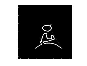
One frame decoded with Matlab of “the Riddle” animation found in the Photolexicon site.
On this post I will concentrate on the ILD file format as it’s the main way the galvo movements data, color and blanking information are stored and transmitted. I found the latest ILD file format description that includes all the types of frames commonly used in the wild. The file format is pretty simple and mostly just a collection of coordinates stored with a header. This web page describes graphically all the frame format and also points at a internal feud in the community going on for years.
All comes from the fact that the color information was poorly integrated in the original format so most of the old files rely on some default palette to choose the color of each point. These default palettes are not completely standard and can change with the software implementation. So to solve the issues the ILDA introduced new format (Frame types 4 & 5) that define 24bits full color for each point.

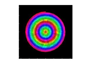
8bit Palette Frame (left) and true color palette on the right (source)
Long story short, I’ve created a ILD file decoder for Matlab with a few examples data files (see at the bottom of the post). I’ve not tested it with Octave but as I’m not using any specific functions it should be pretty much portable. The reader has been optimized to load all the points/colors of a frame with one “fread” call. This enable a very fast decoding (The Riddle file ~20Mb for 5120 images is decoded on my PC in less than 4 seconds).
In an future article I will explore more the galvo tuning principles using the ILDA test patern (available here). The interesting part is that the blue circle is defined outside the square but with a proper tuning is should appears tangent inside the circle. The ILDA used this trick to standardize the dynamic behavior of the scanners mirror servos.
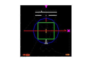
The left picture is the content of the ILDA test frame.
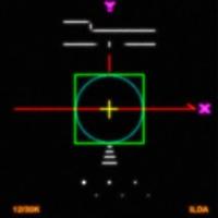
The right picture is the proper result expected from a well tuned scanner (source)
Note: All ILD pictures in this post were generated using the Matlab decoding package available HERE, all code are copyrighted, only usable for non-commercial purpose and provided as is with no guaranty of any sort,
[<<Prev. – Scanner Architecture] [3D Scanner articles] [First Steps: the galvo & laser – Next>>]

 Anyway I think the next step for this weekend is to build a Sound-card to galvo driver adapter to be able to draw some figures!


