The challenge
I’ve done some test prints for someone in the jewel industry. They wanted to see the Form1 quality output to maybe use it as a quick prototyping desktop station and get faster development cycles. We discovered that in some conditions JewelCAD is only capable of exporting to STL the positive geometries OR the negative geometries (holes / notch) but not the fused triangle mesh.
The only way to merge both negative and positive geometry is apparently to slice the object and export it as SLC file. This file format was created in 1994 by 3D systems and is now at the second revision. The evolution was mainly to store the data as binary to save space but the content of the file was not changed much.
Preform is unfortunately not capable of reading SLC files nor importing positive and negative bodies to form a finite model. That’s another instance where it would be handy to have the Printer protocol open or at least an API to build our own slicer for the Form1.
Workaround proposals
I can see two ways to solve this challenge:
- Use a 3D modeling software to apply the boolean operation
- Re-constuct the STL triangle mesh from the SLC slices data
The first option can be done using the free software Blender (see this video tutorial for example). Boolean operations on complex triangles mesh are some time not possible to apply. It’s especially true if the original geometries are not completely clean (holes / inverted triangles…). In the case of my test print, Blender and Netfabb were not able to apply the subtraction.
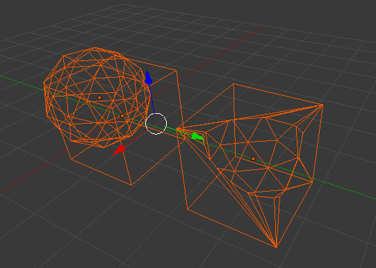
The picture under is showing that even in a very simple case, subtracting a sphere from a cube in Blender creates a lot of extra triangles. The whole difficulty is to generate precisely the cut/intersection line as explained in this paper by Biermann and Al.
So if the Boolean operation is not possible, we can only regenerate the STL triangles from the SLC data. Provided the original geometry slice thickness was at least the desired print configuration, it should not affect the output quality. Commercial software like SLC2STL or Netfabb seems to be able to perform the conversion but the licenses are expensive for a casual usage (in the $k range).
As the triangle geometry is an interesting algorithm development, I have no option but add it to my TODO list! The first step of this un-slicer is of course to read the SLC data.
Matlab SLC file reader
The SLC format is a simple collection of slices composed of a collection of boundaries. You can read the format specification [here]. Each boundary is a closed polygon (poly-line) defined by a series of [X,Y] vertices with the first point duplicated at the end to close the loop.
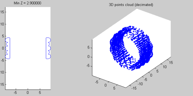
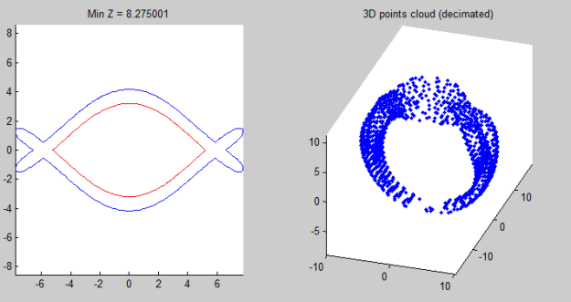
I’ve built an viewer in Matlab to explore the content of SLC v2 files. The archive contains 2 example ring slices SLC file. After extracting all the information, the viewer displays a 2 plot window were the user can click on any point in the 3D plot on the right to display the full slice on the left pane.
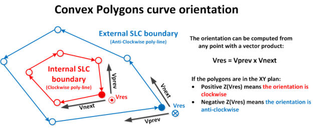
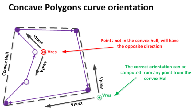
The second picture is showing that external (blue) and internal (red) boundaries are drawn in 2 colors. In the SLC format, internal boundaries are stored clockwise while external boundaries are anti-clockwise. Detect reliably the orientation of a poly-line curve is tricky as it must work for concave polygon. The easiest method is to find one point of the convex hull and use a determinant to get the local convexity…
What’s next?
So while we could dream to have Preform reading the slice directly, it’s probably easier to get one of these software to convert the SLC to STL. This operation is definitely not obvious with many steps to get it working is all circumstances so I probably won’t tackle it anytime soon…
[<<Prev. – Episode 2 : Form1 calibration] [3D Printer articles] [Precision VS Accuracy – Next>>]
